Demystifying yamaha immobilisers
Introduction
In this post I will explain you how does the yamaha motorbike immobiliser system work (only tested on the yamaha mt-07 2017).
For the thieves out there, you can just purchase an immobiliser emulator from aliexpress, plug and play, easy peasy; for the curious ones, continue reading.
Background
Last year, as a proud member of the electronics department of the UJI motorsport team I was charged with the task of testing the proper functioning of our immobiliser emulator unit.
Our team was a fairly young team, and as such, we worked on a limited budget and could not afford a custom ECU. We were forced to use the stock yamaha ECU which as well as being quite hard to tune requieres a paired immobiliser to start up. We were having problems starting up the engine and this little mysterious black box was easy to blame to, thats why I decided to look at its inner workings.
Immobiliser system
The yamaha immobiliser system is compounded of three parts: 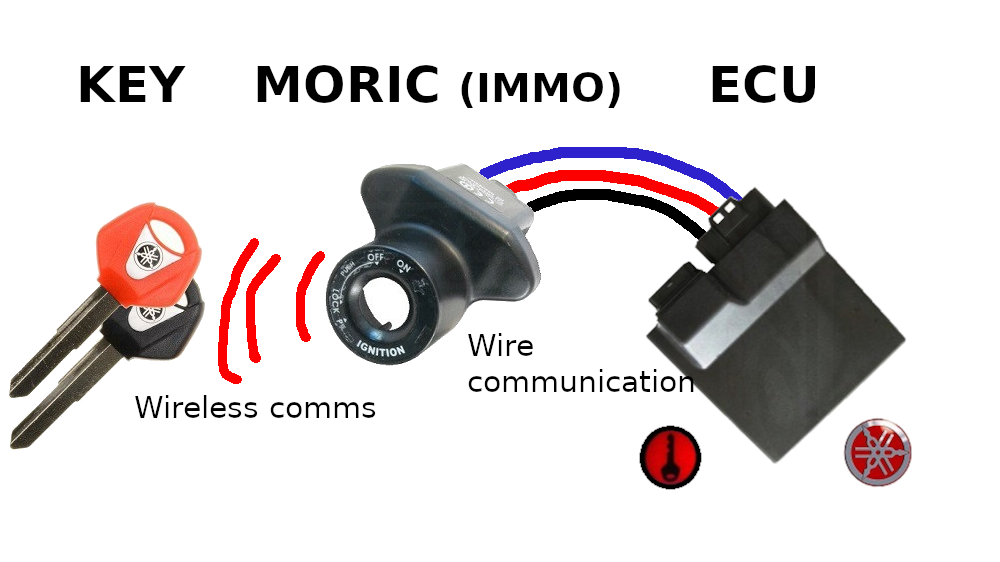
- Yamaha keys, two colors, red ones are for programming and black ones for daily use
- MORIC(IMMO), Immobiliser + power switch
- ECU, controls the motorbike, ignition timing, mixture…
From this setup one would expect the immo to be just a mere transducer, replying signals from the keys to the ECU, but this is not the case. MORIC authenticates keys, and if they are correct it authenticates with the ECU.
Thats why the MORIC can be replaced by an emulator which acts like a MORIC but does not check any key. Each ECU theoretically is paired only with one MORIC, according to yamaha service manuals, in case of losing the red key, the only solution is to replace both ECU and MORIC by a new one. ECUs without a paired MORIC are commonly known as virgin, and they price range starts at 100€.
This means that each ECU is paired with one immobiliser. On power up, the immobiliser unlocks the ECU only if the proper key is present and the motorbike is capable of starting up.
Immobiliser wiring
The MORIC is composed of two elements detached on the schematic, the power switch (2 terminals, 3 wires) and the Immobiliser unit (1 terminal, 5 wires)
The power switch has the following wiring:

From top to down:
- Red/White: 12v, battery
- Brown/Blue: Motorbike main power
- Brown/Red: Motorbike lights
The motorbike power switch has the following positions:
- P: parking mode, only lights are powered up, immo does not power up and bike cannot start.
- LOCK: same as off, but direction is locked.
- OFF: everything is powered off. (except some elements which are wired directly to the battery)
- ON: everything is powered on, immobiliser unlocks ECU and bike can start.
And the immobiliser unit has the following wiring:

From top to down:
- Black: GND, not really interesting
- Yellow/Blue: k-line, bidirectional communication with ECU, 12v HIGH, 0v LOW
- Red/White: 12v, only powered when the power switch is in the ON position.
- Green/Black: Connected to the immobiliser dash light
- Red/Green: 12v, always connected
ECU unlocking
Immo - ECU comms
As remarked by somebodynobody here the communication is performed using UART in half-duplex mode over one wire (with a 12V logic level). The transmission data is: baud rate: 15625 bits/s, no parity bit, 1 stop bit.
Sniffing the k-line
Sniffing the k-line is trivially done with an arduino, I used a teensy, here is the code used:
DANGER!!!
DANGER!!!
DANGER!!!
you need a level converter to bring down the 12V to something manageable by your arduino
1
2
3
4
5
6
7
8
9
10
11
12
13
14
15
16
17
18
19
20
21
22
23
24
25
26
27
28
29
#include <Arduino.h>
boolean written = false;
void setup() {
Serial.begin(115200);


Serial8.setRX(34);
Serial8.begin(15625);


}
void loop() {
while (Serial8.available()){
  delay(50);
  int incomingByte = Serial8.read();
  if (!written){
  Serial.print("RX: ");
  }
  Serial.print(incomingByte);
  Serial.print(" ");
     written = true;


}
if (written){
  written = false;
  Serial.println();
}
}
Here there is a trace example:
1
62 62 62 221 122 67 33 187 61 110 125 75 102 156 137 71 71 71 71 28 150 71 71 71 71 28 137 71 71 71 71 28 63 73 73 73 73 36 63 69 69 69 69 20 63 69 69 69 69 20 63 69 69 69 69 20 63 69 69 69 69 20
This trace is not really readable, isn’t it? Thats why I wrote this python script which can transform the trace into a much more readable form, I have also commented each line for clarity:

As we can see the ECU sends a puzzle, which the Immo answers, and then, the motorbike is allowed to start up.
Emulator
All emulators which I have found for sale seem to be based on this one. There is not really much to say about it, it emulates the immobiliser pretty well. Its basically an Attiny2313 connected to the k-line through an ISO 9141 interface answering the puzzles correctly.
Puzzle answer algorithm
The puzzle answer algorithm as published by somebodynobody is as follows:
1
2
3
out1 = ( int ((( pzl1 * pzl2 ) + ( pzl1 * pzl3 ) + ( pzl2 * pzl3 )) / 0x1000 )) + 0x80
out2 = (( int ((( pzl1 * pzl2 ) + ( pzl1 * pzl3 ) + ( pzl2 * pzl3 )) / 0x40 )) % 0x40 ) + 0x80
out3 = ((( pzl1 * pzl2 ) + ( pzl1 * pzl3 ) + ( pzl2 * pzl3 )) % 0x40 ) + 0x80
outX are each one of the output puzzle bytes and pzlX are each one of the input puzzle bytes
Conclusion
I’m not really sure of what where the design considerations taken by yamaha, but this system is clearly flawed when its 20 times cheaper to obtain an emulator than to go to the official store in case of red key lose.
References
- This Digital Kaos post by a user called somebodynobody
- YAMAHA MT-07 2016 service manual and wiring schematic
- Python decode script
- VAG / Yamaha emulator files